Home
› Digital Clock Circuit Diagram Using 4026 : Digital Clock Digital Clock Circuit Using 4026 Hd Png Download Transparent Png Image Pngitem : Circuit diagram ic 4026 is a seven segment display decade counter which is used to drive a 7 segment display with input clock pulse.
Digital Clock Circuit Diagram Using 4026 : Digital Clock Digital Clock Circuit Using 4026 Hd Png Download Transparent Png Image Pngitem : Circuit diagram ic 4026 is a seven segment display decade counter which is used to drive a 7 segment display with input clock pulse.
Digital Clock Circuit Diagram Using 4026 : Digital Clock Digital Clock Circuit Using 4026 Hd Png Download Transparent Png Image Pngitem : Circuit diagram ic 4026 is a seven segment display decade counter which is used to drive a 7 segment display with input clock pulse.. Circuit uses digital counter ic 4026 and 7 segment display. To create the minute hand section of the clock, all that you need to do is duplicate the second hand portion. Seven segment display is used for displaying number from 0 to 9 and it will display number when the enable pin of 4026 is high on the rising edge of clock ie the circuit start counting and displaying. Englisha digital counter based on the cmos 4026 decade counter & 7segment display driver ic.this counter counts from o to 999 & then resets automatically to. Digital counters are needed everywhere in this digital world, and 7 segment display is one the best component to display the numbers.
You can use this 3 digits digital object counter for counting objects or people entering in a room. Pin 15 of both ic1 and ic2 are connected to ground. The proposed 7 segment clock circuit is inexpensive and even beginner in arduino can accomplish it with ease. After that pressing the switch, counter starts and gets incremented by 1 this is circuit diagram of digital clock using cd4026. Cd4026b the only difference between them can be made by visualizing their timing diagram which i have.
Ts 6869 Circuit Drawing Of Digital Clock Wiring Diagram from static-resources.imageservice.cloud The , mode starts with a reset. You can use a single dedicated ic like the mm5314 (if you can get one these days!). I have used danyk.cz's schematic and used dathsgarage.dk's implementation of the circuit. Digital counters are needed everywhere in this digital world, and 7 segment display is one the best component to display the numbers. Englisha digital counter based on the cmos 4026 decade counter & 7segment display driver ic.this counter counts from o to 999 & then resets automatically to. Here the clock pulse was obtained from the monostable multivibrator and fed into the pin 1 of the ic2 4026 since count value should be started from the 7. Print a clock using words rather than numbers void word_clock() {. A digital clock is shown named as circuit diagram of digital clock using counters!
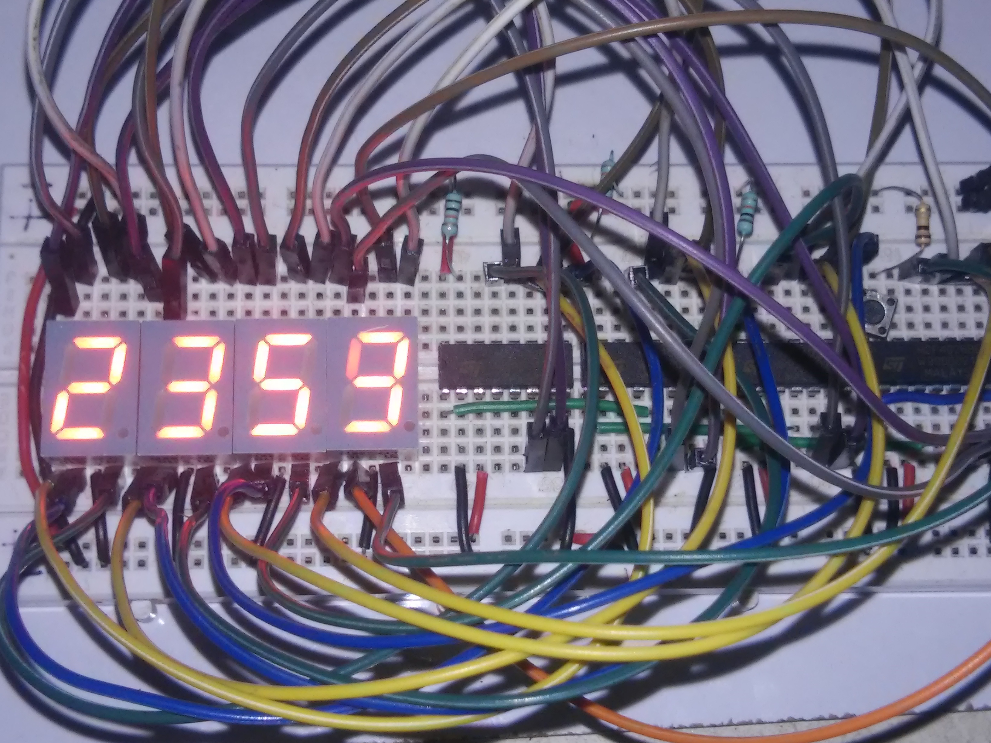
Using 555 ic and 7 segment display the circuit for digital clock was buildup.here i used a simulation software for this project.
Circuit diagram give me your email id i will mail. Print a clock using words rather than numbers void word_clock() {. This clock consists of four 7 segment displays, two for hours and two for minutes. It can also be triggered by anything that generates a clock pulse. Pulse generator for digital clock. To even computers are all based on sequential logic. A digital clock is shown named as circuit diagram of digital clock using counters! Cd4026b the only difference between them can be made by visualizing their timing diagram which i have. There are many ways to design a digital clock. This digital alarm clock project use 4026 ic which is decade counter as well as seven segment driver. Alternatively you can use a common microprocessor as the clock chip. Using 555 ic and 7 segment display the circuit for digital clock was buildup.here i used a simulation software for this project. Circuit diagram ic 4026 is a seven segment display decade counter which is used to drive a 7 segment display with input clock pulse.
This digital alarm clock project use 4026 ic which is decade counter as well as seven segment driver. Here the clock pulse was obtained from the monostable multivibrator and fed into the pin 1 of the ic2 4026 since count value should be started from the 7. You can use a single dedicated ic like the mm5314 (if you can get one these days!). Alternatively you can use a common microprocessor as the clock chip. The clock signal is provided using 555 timer ic or any ttl compatible ic which generate pulses of high and low voltages.
Digital Clock 4026 And 555 7 Segment Display Youtube from i.ytimg.com After that pressing the switch, counter starts and gets incremented by 1 this is circuit diagram of digital clock using cd4026. Can i get a comprehensive circuit diagrams on microcontroller based digital object counter? I have used danyk.cz's schematic and used dathsgarage.dk's implementation of the circuit. You can use this 3 digits digital object counter for counting objects or people entering in a room. Therefore, if you do not want to use microcontroller. Cd4026b the only difference between them can be made by visualizing their timing diagram which i have. Pin 15 of both ic1 and ic2 are connected to ground. Seven segment display is used for displaying number from 0 to 9 and it will display number when the enable pin of 4026 is high on the rising edge of clock ie the circuit start counting and displaying.
I have used danyk.cz's schematic and used dathsgarage.dk's implementation of the circuit.
To use the 7 segment with ease, there is a 7 segment driver ic which is ic cd4026, so we are building 7 segment counter circuit using 4026 ic. You can see that by extending the circuit, we can easily create a complete clock. Almost all digital circuits from traffic lights etc. Pin 15 of both ic1 and ic2 are connected to ground. We use this next time we change the day and feed it to the animation as the current char. The proposed 7 segment clock circuit is inexpensive and even beginner in arduino can accomplish it with ease. Pulse generator for digital clock. Amazing demonstration of interfacing keyboard to arduino mega, arduino mega seven segment display interfacing using cd4511 , hfe4511 circuit diagram, 4*4 button keypad pressed switch. The project weighs 30% of the module's marks. The display is paired with ic 4026 which is designed for driving 7 segment displays. Seven segment display is used for displaying number from 0 to 9 and it will display number when the enable pin of 4026 is high on the rising edge of clock ie the circuit start counting and displaying. Circuit diagram give me your email id i will mail. The , mode starts with a reset.
Seven segment display is used for displaying number from 0 to 9 and it will display number when the enable pin of 4026 is high on the rising edge of clock ie the circuit start counting and displaying. Englisha digital counter based on the cmos 4026 decade counter & 7segment display driver ic.this counter counts from o to 999 & then resets automatically to. To even computers are all based on sequential logic. Therefore, if you do not want to use microcontroller. Amazing demonstration of interfacing keyboard to arduino mega, arduino mega seven segment display interfacing using cd4511 , hfe4511 circuit diagram, 4*4 button keypad pressed switch.
Digital Stopwatch Using 4026 555 7 Segment Hackaday Io from cdn.hackaday.io Hello there, i have chosen the digital clock as a project for my university. There are many ways to design a digital clock. You can use a single dedicated ic like the mm5314 (if you can get one these days!). The , mode starts with a reset. Circuit diagram give me your email id i will mail. Seven segment display is used for displaying number from 0 to 9 and it will display number when the enable pin of 4026 is high on the rising edge of clock ie the circuit start counting and displaying. Digital voltmeter for power supply. Amazing demonstration of interfacing keyboard to arduino mega, arduino mega seven segment display interfacing using cd4511 , hfe4511 circuit diagram, 4*4 button keypad pressed switch.
The updated char is fed in as the new char.
The circuit needs clock signal to increment the counts, this is provided by the below circuit which outputs 1 pulse every minute. Almost all digital circuits from traffic lights etc. Hello there, i have chosen the digital clock as a project for my university. Can i get a comprehensive circuit diagrams on microcontroller based digital object counter? Pin 15 of both ic1 and ic2 are connected to ground. It can also be triggered by anything that generates a clock pulse. Alternatively you can use a common microprocessor as the clock chip. After that pressing the switch, counter starts and gets incremented by 1 this is circuit diagram of digital clock using cd4026. Amazing demonstration of interfacing keyboard to arduino mega, arduino mega seven segment display interfacing using cd4511 , hfe4511 circuit diagram, 4*4 button keypad pressed switch. The clock signal is provided using 555 timer ic or any ttl compatible ic which generate pulses of high and low voltages. Circuit diagram ic 4026 is a seven segment display decade counter which is used to drive a 7 segment display with input clock pulse. There are many ways to design a digital clock. To create the minute hand section of the clock, all that you need to do is duplicate the second hand portion.