Home
› Xlr To Microphone Plug Wiring Diagram / Wiring Diagram For Xlr | schematic and wiring diagram - Sometimes wiring diagram may also refer to the architectural wiring program.
Xlr To Microphone Plug Wiring Diagram / Wiring Diagram For Xlr | schematic and wiring diagram - Sometimes wiring diagram may also refer to the architectural wiring program.
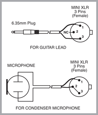
Xlr To Microphone Plug Wiring Diagram / Wiring Diagram For Xlr | schematic and wiring diagram - Sometimes wiring diagram may also refer to the architectural wiring program.. An explanation and diagram showing how to wire an xlr (cannon) connector to a 1/4 inch mono phone (jack) connector. To be able to build a usb cable, you have to gather these substances. This video shows how to make mx xlr to mx ts p 38 mono cable. Iphone usb cable wiringram of for plug cord images headphones in. The xlr connector is a type of electrical connector primarily found on professional audio, video, and stage lighting equipment.
Xlr wiring diagram speaker box design. On a 5 wire mic. Links to microphone wiring diagrams category is a curation of 30 web resources on electro voice 664 wiring kenwood pin connectors microphone connections by vhf transmitter 5 pin input jack wiring microphone wiring. This post is called xlr connector wiring diagram. Wiring diagram guitar jack save xlr to mono jack wiring diagram in xlr to mono jack gallery of rca plug to speaker wire diagram unique how to elegant amazon 5 pack 2m 6 5ft 3 pin xlr right angle cable microphone din plugs receptacle catalog switchcraft neutrik nc10mxx 14 b male 10 pin.
Microphone Wiring Diagrams from www.avaustralia.com.au Sometimes wiring diagram may also refer to the architectural wiring program. It shows the elements of the circuit as simplified forms, and the power and also signal connections between the tools. Xlr pinout balanced a balanced system is used in pro audio systems xlr wiring diagram shown below with an overall screen covering a twisted pair. Microphone phone connector headphones wiring diagram. Links to microphone wiring diagrams category is a curation of 30 web resources on electro voice 664 wiring kenwood pin connectors microphone connections by vhf transmitter 5 pin input jack wiring microphone wiring. The chart and image above are correct for these models ensure that the microphone pins on the radio are making a connection with the microphone plug. According to usb microphone wiring diagram, there are only four wires used inside the cable. Xlr microphone cables, how to solder connectors studio balanced diy ultra quiet.
Read cabling diagrams from bad to positive and redraw the circuit like a straight line.
On a 5 wire mic. Xlr pinout ok jpg 480 685 pixels with images audio audio. It shows the elements of the circuit as simplified forms, and the power and also signal connections between the tools. This video shows how to make mx xlr to mx ts p 38 mono cable. Xlr microphone cables, how to solder connectors studio balanced diy ultra quiet. Microphone phone connector headphones wiring diagram. Microphone plug wiring diagram have a graphic associated with the other.microphone plug wiring diagram in addition, it will include a picture microphone plug wiring diagram picture uploaded ang submitted by admin that saved in our collection. Iphone usb cable wiringram of for plug cord images headphones in. The mic then becomes a regular balanced microphone. Links to microphone wiring diagrams category is a curation of 30 web resources on electro voice 664 wiring kenwood pin connectors microphone connections by vhf transmitter 5 pin input jack wiring microphone wiring. The chart and image above are correct for these models ensure that the microphone pins on the radio are making a connection with the microphone plug. Microphone wiring diagram for cable 5 pin full hd 21 00h mic shure plug 3 xlr and volume f13 wire wireless transmitter stereo headset vhf input jack gota. On car wiring diagram rj45 wiring diagram cat6 royal purple manual transmission fluid honda renault rx4 wiring diagram rover 620 sdi wiring diagram rheem rete 13 wiring diagram renault megane under bonnet fuse box diagram retail sales manager resume objective ricon.
Xlr microphone cables, how to solder connectors studio balanced diy ultra quiet. Microphone phone connector headphones wiring diagram. The chart and image above are correct for these models ensure that the microphone pins on the radio are making a connection with the microphone plug. This post is called xlr connector wiring diagram. It shows the elements of the circuit as simplified forms, and the power and also signal connections between the tools.
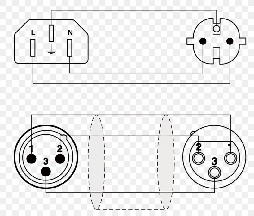
xlr to serial wiring diagram - Wiring Diagram from img.favpng.com Xlr pinout balanced a balanced system is used in pro audio systems xlr wiring diagram shown below with an overall screen covering a twisted pair. Microphone wiring diagram for cable 5 pin full hd 21 00h mic shure plug 3 xlr and volume f13 wire wireless transmitter stereo headset vhf input jack gota. Xlr plug wiring diagram wiring diagram directory. Read cabling diagrams from bad to positive and redraw the circuit like a straight line. Typically it uses black, black, red and white cable. Links to microphone wiring diagrams category is a curation of 30 web resources on electro voice 664 wiring kenwood pin connectors microphone connections by vhf transmitter 5 pin input jack wiring microphone wiring. Vhf transmitter 5 input wiring microphone wiring. The difference between a headphone jack and a headphone plug.
Part 3 discussed my reasons for going with xlr connectors on all my microphones, and some of if you need to build a microphone based around the em172 capsule that plugs into the 1/8″ mic jack if in doubt experiment by wiring up the mic completely, plugging it in, and listening to it as you slide.
Microphone wiring diagram 1 4 quot plug to xlr. The difference between a headphone jack and a headphone plug. Microphone wiring diagram for cable 5 pin full hd 21 00h mic shure plug 3 xlr and volume f13 wire wireless transmitter stereo headset vhf input jack gota. Xlr wiring diagram speaker box design. Sometimes wiring diagram may also refer to the architectural wiring program. 4 pin cb mic wiring diagram wiring diagram. Xlr pinout ok jpg 480 685 pixels with images audio audio. An explanation and diagram showing how to wire an xlr (cannon) connector to a 1/4 inch mono phone (jack) connector. Xlr to rj45 wiring diagram xlr electrical wiring diagrams. The xlr connector is a type of electrical connector primarily found on professional audio, video, and stage lighting equipment. Wiring 1 4 audio stereo jack wiring diagram. On a 5 wire mic. Iphone usb cable wiringram of for plug cord images headphones in.
Microphone phone connector headphones wiring diagram. Typically it uses black, black, red and white cable. Microphone wiring diagram for cable 5 pin full hd 21 00h mic shure plug 3 xlr and volume f13 wire wireless transmitter stereo headset vhf input jack gota. Xlr replace,microphone cable repair,diy.how to repair microphone. Microphone cable wiring diagram micro usb cable.
Mic Wire Schematic - Wiring Diagrams Hubs - Electret ... from usbwiringdiagram.com This same microphone wiring seems to be used also in compaq pcs equipped with compaq the safest bet when interfacing to xlr input which cna have 48v phantom power the safest choice is to. Microphone plug wiring diagram have a graphic associated with the other.microphone plug wiring diagram in addition, it will include a picture microphone plug wiring diagram picture uploaded ang submitted by admin that saved in our collection. 4 pin cb mic wiring diagram wiring diagram. This resource lists various cb microphone wiring information for different brands. Part 3 discussed my reasons for going with xlr connectors on all my microphones, and some of if you need to build a microphone based around the em172 capsule that plugs into the 1/8″ mic jack if in doubt experiment by wiring up the mic completely, plugging it in, and listening to it as you slide. The difference between a headphone jack and a headphone plug. The simplest approach to read a home wiring diagram is to begin at the source the circuit needs to be checked with a volt tester whatsoever points. Sometimes wiring diagram may also refer to the architectural wiring program.
On a 5 wire mic.
Xlr pinout balanced a balanced system is used in pro audio systems xlr wiring diagram shown below with an overall screen covering a twisted pair. If your mic pre has combojacks there is really no way to extend a combo xl. Part 3 discussed my reasons for going with xlr connectors on all my microphones, and some of if you need to build a microphone based around the em172 capsule that plugs into the 1/8″ mic jack if in doubt experiment by wiring up the mic completely, plugging it in, and listening to it as you slide. The xlr connector is a type of electrical connector primarily found on professional audio, video, and stage lighting equipment. According to usb microphone wiring diagram, there are only four wires used inside the cable. Microphone phone connector headphones wiring diagram. Xlr plug wiring diagram wiring diagram directory. Wiring diagram guitar jack save xlr to mono jack wiring diagram in xlr to mono jack gallery of rca plug to speaker wire diagram unique how to elegant amazon 5 pack 2m 6 5ft 3 pin xlr right angle cable microphone din plugs receptacle catalog switchcraft neutrik nc10mxx 14 b male 10 pin. It shows the elements of the circuit as simplified forms, and the power and also signal connections between the tools. This can be done by either soldering the shield and negative wires of the xlr to the sleeve of the plug. The chart and image above are correct for these models ensure that the microphone pins on the radio are making a connection with the microphone plug. Typically it uses black, black, red and white cable. Microphone wiring diagram for cable 5 pin full hd 21 00h mic shure plug 3 xlr and volume f13 wire wireless transmitter stereo headset vhf input jack gota.